
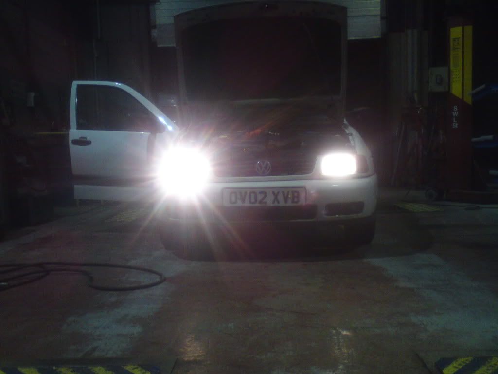
i've got a 4 relay setup - 2 for dip beam and 2 for main beam. to show the difference, i took a pic with one side connected - gues which one has the upgrade and which one is standard wiring! it's taken it from 8.3V at the bulbs with the engine running up to the full 14.3V
all you need is some appropriate sized cable, relays, new headlight connectors (not essential, but lets you do a neater job) and some connectors.
assuming you're running standard bulbs, dip beam wil be 55W each side, which will give a current draw of around 5A. i used cable rated at 8A
with the rocco, you'll have an extra load with main beam if you've still got the inner spots - 60W in the main light and 55W for the spot (assuming you've not put higher power bulbs in. 115W per side will be 10A. make sure you're relays and cable are big enough. slightly too big won't do any harm, but no point in using stupidly oversize cable.
the relays i used were from maplin, and are rated at 40A. order code N00AW £2.29 each

being a later vehicle, it's got a small distribution box sat on top of the battery with 5 large fuses and 3 blade fuses. if you're adding lots of stuff (ICE etc) i'd recommend getting one, as it makes a much neater job of adding stuff to the battery terminals.
H4 connectors are easily obtainable from your favourite autoelec suppliers. i got mine from ebay. go for ones that don't have short wires already attached, and you won't then have to join the cable 4" from the bulb. iirc the inner spots are H7s, so you'll need new a new connector for these too.
you can get relay holders which are similar looking to the headlight plugs, or you can simply use spade connectors directly onto the terminals
the relays have 5 connections. the middle connection won't be used, the 4 we are interested in are labelled 85, 86, 30 and 87B they need to be connected as follows:

85 connects to earth. al i do for this is make a small piece of wire with a spade on one end and a loop on the other. this loop is earthed thru the relay mounting screw when the relay is mounted onto the bodywork. alternatively, run the wire to the battery -ve
86 is the relay control. the +ve that used to feed you headlights now connects here. this will be either yellow or white, depending on whether you're doing the dip or main beam.
87b connects to the battery +ve. this is the new power supply for your headlights, so make sure the cable is up to the job. it also MUST HAVE A FUSE if you're using one of the later battery mounted fuseboxes, this is easy. otherwise fit an inline fuse holder such as these http://www.ebay.co.uk/itm/250889031790. the fuse should be as close to the battery as you can. this is important! if you have a long cable going to the fuse holder and it rubs on the bodywork and wears through to expose the copper conductor, you will have nothing to protect you. the wire will overheat and catch fire!
30 this now connects to the light in place of the wire you have removed
don't forget that your lights also need a good earth connection. i just replaced the brown earth wire at the bulb with a larger one that ran to the battery -ve. you can either leave the original earth at the light for the sidelight, or use it as the relay earth and feed the sidelight from the new headlight earth.
i would suggest feeding left and right via different fuses, so that should one of them blow, you will still have one working headlight
i would suggest keeping wiring colours "standard" so you don't get confused, and to make later fault finding easier should the need arise. earth wires are brown, feed from the relay to the lights is yellow or white. i used red for the permanent supply to the relay to remind me it is a permanent live. relays are easily mounted onto the inner wings just behind the headlights with a couple of self tappers. all new wiring must be secure (mot fail if it isn't!) and it is worth protecting it with some spiral wrap or taping it up like the original loom.
a few words of warning:
take a bit of time to plan all the routing of all the wires before you start.
make sure you have all the parts and tools you need before you start, and get a few extra crimp on connectors as you're bound to mess up at least one.
disconnect the battery before you start (remove -ve first, and reconnect -ve last. that way, should your spanner hit the bodywork when loosening or tightening the +ve you won't get a big spark and an exploding battery)
if you are in any doubt, either take it to an auto electrician (should only take them an hour to do, so not that expensive) or ask for more advice or help on here.
my inner 5 year old will now try to draw some schematics with windows paint...