
a. a bit stupid
b. expensive, as I’d need to buy stuff
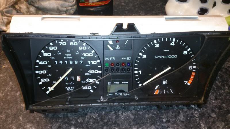
Only 4 of the possible 10 LEDs are used in my car; Indicators, Battery, Oil and Main beam with a spare in the middle on the top row and the entire bottom row are blank. I’ve seen some cars with more of the blanks filled up but I’ve no idea what VW intended for the rest of them.
So I decided I’d have a go at fitting the immobiliser LED that was currently fitted into the blank above the headlight switch.
I had a spare (damaged) set of clock that I’d picked up from a scrappy for a fiver so I had a test run dismantling the clocks, I was also able to trial any drilling before committing to my set.
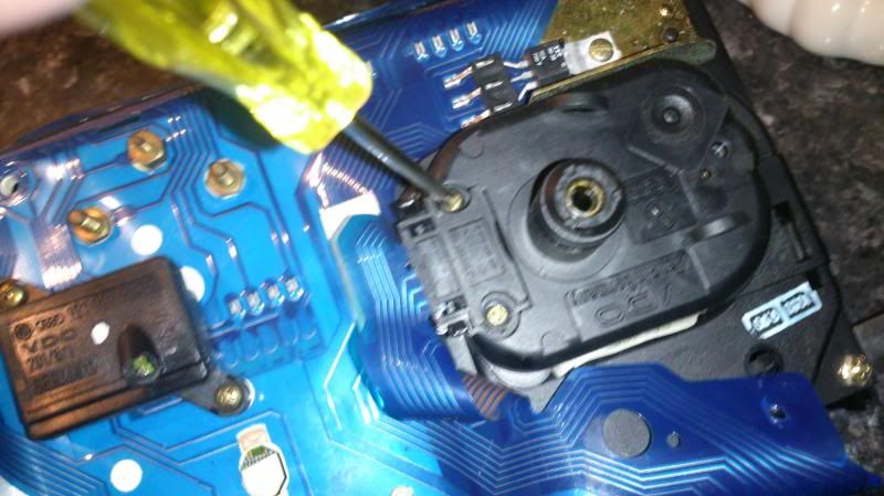
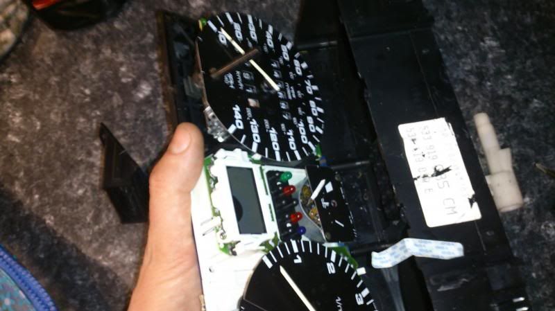
Dismantling the clocks is quite straight forward. The two main plugs (I imagine if you have later clocks that the socket still attaches in the same way) need to be unclipped from body. Gently prise them over the clip and slide them off.
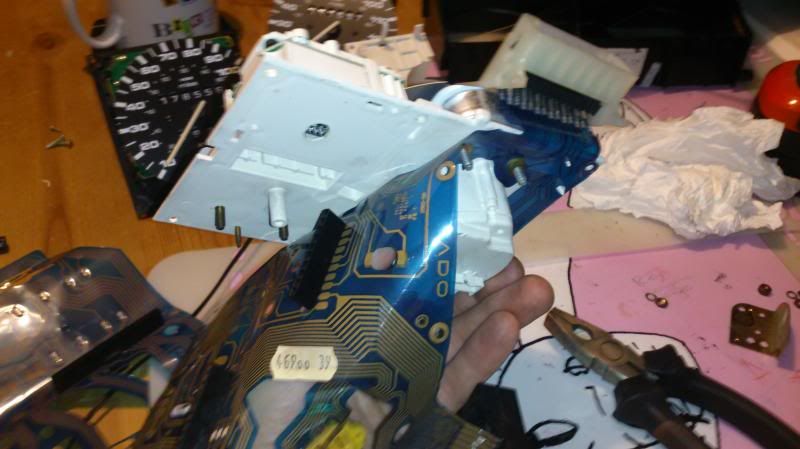
Remove the bulbs by twisting, and then carefully prise the blue pcb off all the retaining pins.
If you have an MFA unscrew the block and remove.

And unscrew the metal corner bracket by the speedo and the screwed in connector.
Then you can undo the 8 main screws and undo the nuts on the back of the fuel and water temp gauges – take care to retain the small washers.
For now leave the long thin plug still attached but unplug the connections on the back of the speedo, just gentle pull them away from the body.
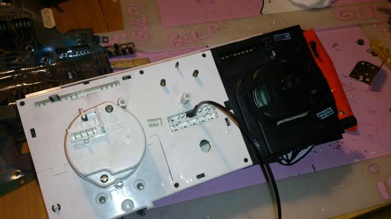
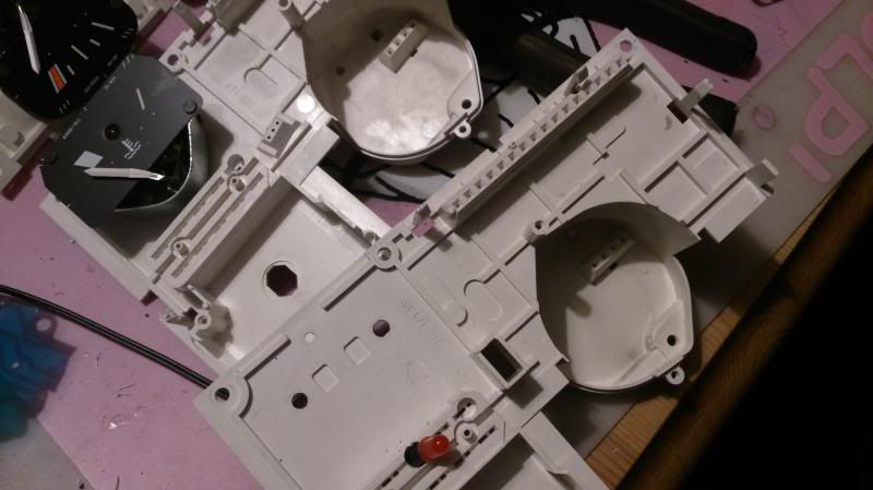
Gently separate the two halves of the body, note the speedo will separate from the other half, carefully place that out of the way.
You should now have the main body of the clocks, minus the speedo, attached to a white plastic back-plate.
You can work with it like this but as I had a spare set of clocks that I’d already drilled I thought going to swap the whole white back-plate so I removed the reset of the hardware from it. It’s easy enough if you want to, again just methodically undo stuff and work with enough space to layout. If you don’t need to dismantle the clock completely I’d still advise removing the water temp gauge just to give you some room to work and remove the risk of damage should you slip later on, lol.
As you’ve already removed the nuts from the back it should just pull through, although it might be a tight fit. Gently apply some pressure and prise it free.
Now you’re getting down to the business bit. But unfortunately as it was getting intense I stopped taking photos so you’ll just need to follow the instructions. This shows the finished item compared to the unmolested cover:
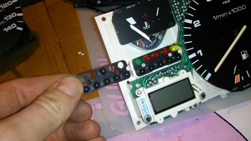
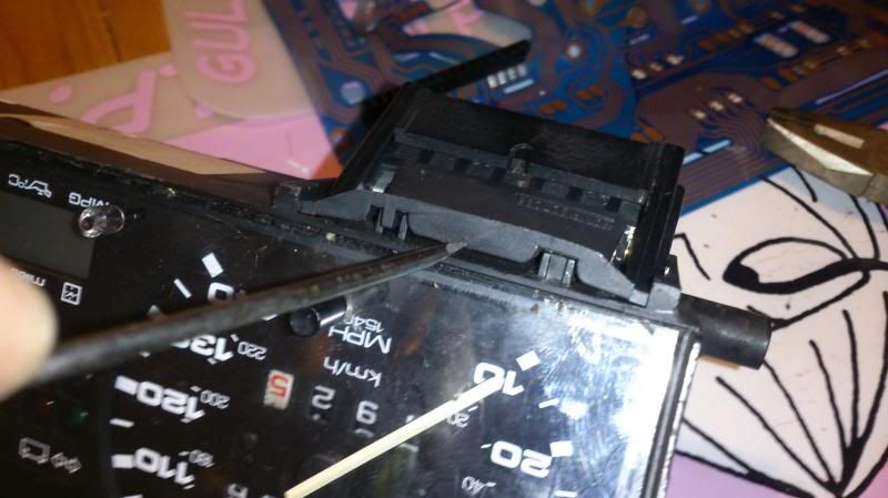
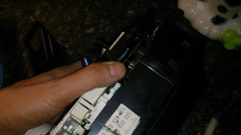
The LEDs are just held in place between the white back-plate and the black cover plate. The cover plate is located on two white pins. Gently (and I mean gently) prise the black cover off the front. You should be able to do this with your fingers but you might get more control with a small screwdriver.
If the central plug is still pushed in at the back this should hold the LEDs in place when you remover the front, but if you’ve unplugged this they will be lose.
The reason you need to be gentle is once this is off the LEDs are quite likely to fall out. If you have later clocks with a BLUE full beam this isn’t an LED, it’s a little ‘grain of wheat’ bulb with a blue cap. Again be careful the blue cap doesn’t fall on the floor never to be seen again!
With the black cover off, you can now, if you haven’t already unplug the block at the back and the the LEDs will come out of the front. You’ll see the how they just push fit. Note the small locating holes are one big and one small and the LEDs should have a kink in one of the legs, this one goes in the larger hole.
First take the black cover and carefully, from behind, drill out the black LED blank that you want to use using progressively larger drill bits. I advise using a variable speed battery drill to give you more control. It’s easy to crack the black cover.
The LED for my immobiliser was already neatly finished with a length of wire, a small plug and neatly heat shrinked. I didn’t want to disturb this so wanted to use the LED and wires exactly as they are. If you’re more comfortable with a soldering iron then from this stage, now you see how it all fits together you might be happy to push fit the LED you want to use and tap into the standard plug with your new wiring. I was not happy with this so wanted to pass my LED through the clocks complete.
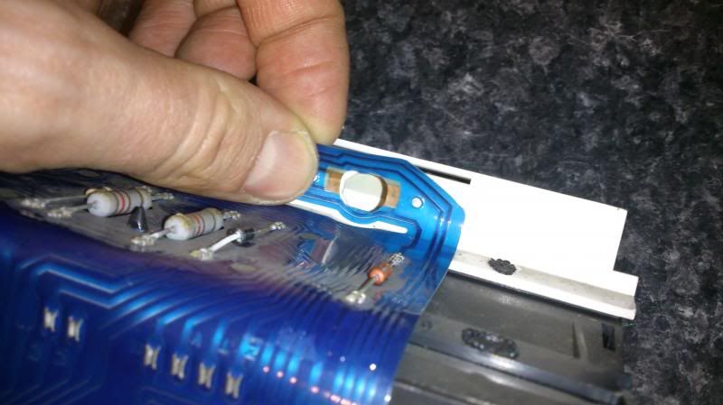
So between the centre-point of the 2 pin holes for the LED location you want to use, drill out the white back-plate.
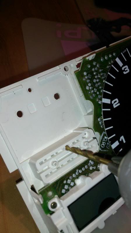
Because the LED needs to come through from the back you need to drill a slightly oversize hole to push the LED base through.
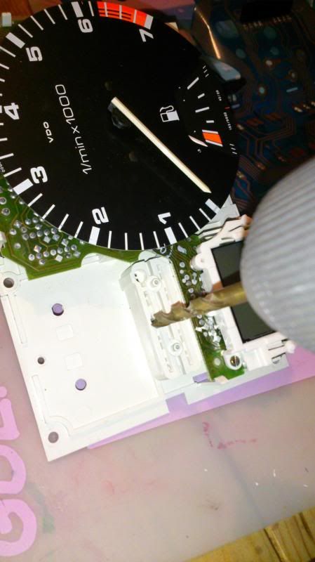
At this point the side wall of the back plate gets very thin. But the advantage to this is once the LED is pushed through you can bend the plastic back in to ‘lock’ the LED in place so it won’t pull through the back at a later stage. If in doubt you could always put a dab of glue on but I didn’t find this necessary.
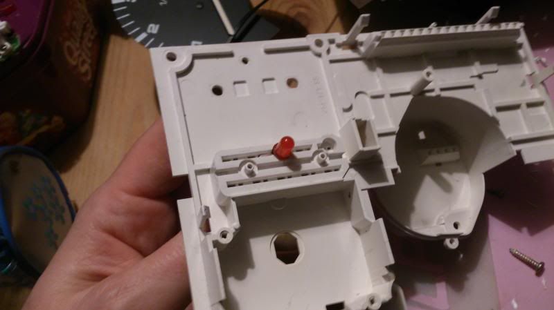
Passing the new LED through from the back, with the trailing wire:
Now you need to deal with the plug and the PCB, as the plug goes full length. The centre of the plug is blank so carefully cut them away with a sharp Stanley or junior hacksaw. Separating the plug into 2 parts, then cut a small split in the PCB to pass the wire through.
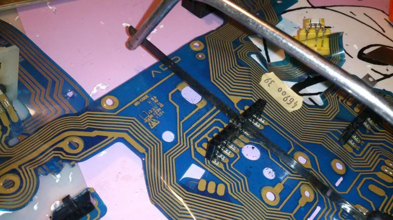
If you use the bottom row you won’t need to cut the plug, just make a hole in the PCB.
Now carefully put it all back together, but before you do you might want to give it all a clean. I cleaned the inside of the lens, gently wiped the clock faces and also cleaned all of the bulbs before I put them back in. The lights are SOOOOOOOOO much brighter from just being clean that LED replacement or upgraded blubs are not actually required!
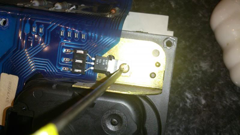
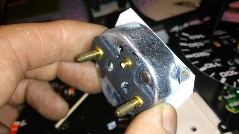
Oh, and when re-fitting don’t over tighten the water temp gauge especially the thinner middle leg or this might happen, luckily I had a spare:
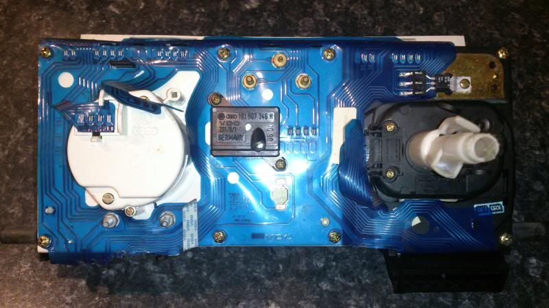
Things to note: My original clocks are 86 and the spares I had were 90. I did a test run on the white bit and drilled it through and was planning on swapping the casings so I had an unmolested shell should I ever need to put it back. But once I got to that stage I discovered the MFA plug was at a different angle so I could use it. The MFA body on my early clocks is metal but on the later ones it’s plastic. I guess a sign of VW cutting costs on later cars. The plastic one was broken.
Notice the large open rectangle to the right of the LED on the 90 clocks and the 3 angled pin holes on the early clocks behind.
And although the later clocks gave me a bulb and cap for blue main beam I decided to keep with my original yellow LED.
So now you know how to, and with still 5 spare slots the world is your oyster.... what other little warning lights do you fancy adding lol.
[youtube]<iframe width="560" height="315" src="//www.youtube.com/embed/YmWKvaVGHG4" frameborder="0" allowfullscreen></iframe>[/youtube]